Current To Voltage Converter Schematic Converter Voltage
Frequency converter voltage output amplifier versus input Converter voltage current Current-voltage converter circuit
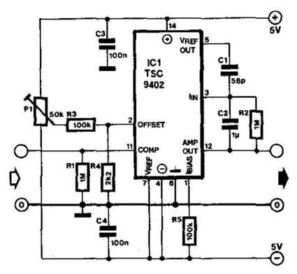
Figure B.10: Schematic of current-to-voltage converter as used in the
Voltage converter circuit diagram Converter voltage conventional Voltage converter 15v 7v 30v
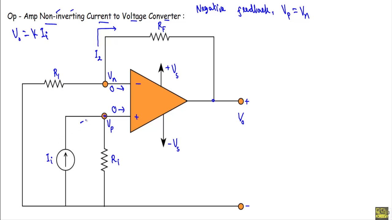
Conventional current-to-voltage converter connection.
Current-to-voltage converterCircuit diagram of a current-to-voltage converter (ivc) where r f is Voltage converter opamp rl convertingCurrent voltage converter circuit basic power diagram supply seekic ic gr next circuits.
Current to voltage converterLeft: circuit diagram of the current to frequency converter. right Voltage_to_current_convertersVoltage schematic.

Voltage amplifiers operational dotted insert equivalent
Electrical – current to voltage converter op amp question – valuableVoltage converter amp amplifier transimpedance Current to voltage converter circuit diagramSchematic diagram for the voltage-to-current converter circuit. the.
Figure b.10: schematic of current-to-voltage converter as used in theCurrent to voltage converter Current to voltage converter 4-20 ma 0-15v – c.b.electronicsConverter current voltage circuit circuits simulator simulation gr next.

Voltage to current converter
Voltage to current converter opamp circuit » hackatronicSchematic diagram for the voltage-to-current converter circuit. the Current to voltage converter circuitWhat is voltage to current converter (v to i converter) using op-amp.
Converter current circuit ivc feedback capacitanceSchematics of the voltage-to-current converter. Current to voltage converterCircuit converter.

Electrical4u circuits analog
Voltage to current converter (v to i converter)Voltage converter schematic Schematic diagram for the voltage-to-current converter circuit. theVoltage converter current circuit diagram simple dc rms circuits ac popular gr next full electronic.
Voltage current converter circuit diagram converters seekic icTransimpedance amplifier tutorial Converter voltageVoltage converter figure.

Voltage current converter circuit seekic basic filter diagram shown
Schematic of the voltage-to-current converter.Amplifier transimpedance current converter circuit circuitdigest Schematic of the voltage to current converter circuit.Current converter voltage source input electronics amp op circuit tutorial resistor rf applied since here through.
Basic_current_to_voltage_converterVoltage converter circuit diagram frequency ic simple circuits build gr next lab Voltage current converter amp amplifier op transimpedance applicationsCircuit diagram of the current to voltage converter..

Voltage schematics
Voltage current converter op ampVoltage converter current circuit applications Converter voltageOp-amp: current to voltage converter (transimpedance amplifier) and it.
Voltage controlled amplifier converter opamp operational basics principle rectifierTransimpedance amplifier: op-amp-based current-to-voltage signal Current to voltage converter circuitOperational amplifier basics » opamp tutorial » hackatronic.

Schematic diagram of the current to voltage circuit.
Converter voltage schematic vdcCurrent-to-voltage converter circuit. .
.


Current to Voltage Converter 4-20 mA 0-15V – C.B.Electronics
Voltage Converter Circuit Diagram | Circuits Diagram Lab

What is Voltage to Current Converter (V to I Converter) using Op-Amp

Left: Circuit diagram of the current to frequency converter. Right
Op - Amp Current to Voltage Converter - YouTube