Ct And Pt Connection Diagram Instrument Transformer Ct & Pt
Instrument transformers: what is it? (and their advantages) Wiring connection Digital ammeter wiring diagram and connection with ct
The Electrical Portal: Difference between CT and PT
Electrician's journal-understanding potential transformers Electrical systems: july 2012 [diagram] 12470 3 phase 4 wire high side diagram
Wye potential circuit three neutral monitoring using pt wire transformers control continental systems without figure
Potential transformer (pt)Ct and pt connection diagram explained Ct and pt connection diagram explainedElectrical 3 phase energy meter wiring connection.
Electric meter wiring diagramCt and pt connection diagram explained etechnog, 49% off Ct and pt connection diagram explainedPt connection transformer potential instrument transformers electrical diagram advantages electrical4u power their showing primary engineers hyderabad institute.

Ct and pt circuit diagram
Ct metering wiring diagramCt.pt. connection diagram Instrument transformer ct & ptElectrical engineering mcq questions and answers.
A clear diagram of 11kv ct pt meter connectionHt line ct pt with ht meter connection diagram|| ct/pt to transformer Ct wiring diagramDigital ammeter wiring with current transformer.

Ct block diagram
Transformer energy connection diagram cts vts racecar instrument settings wrong smartCt and pt connection diagram explained etechnog, 56% off Why pt and ct terminals are star connectedThe electrical portal: difference between ct and pt.
Great 3 phase energy meter connection diagram with ct and pt 7 coreElectrical topics: circuit diagram of loaded current transformer and Wazipoint engineering science & technology: 09/17/1511kv ht metering connection with ct pt.

Circuit diagram of ct
Ct vt connection pt electrical measuring burden mainStar pt ct connected terminals why electrical4u 11kv high voltage ht metering connection with ct & ptTransformer current diagram circuit potential loaded electrical connected typical transformers standard.
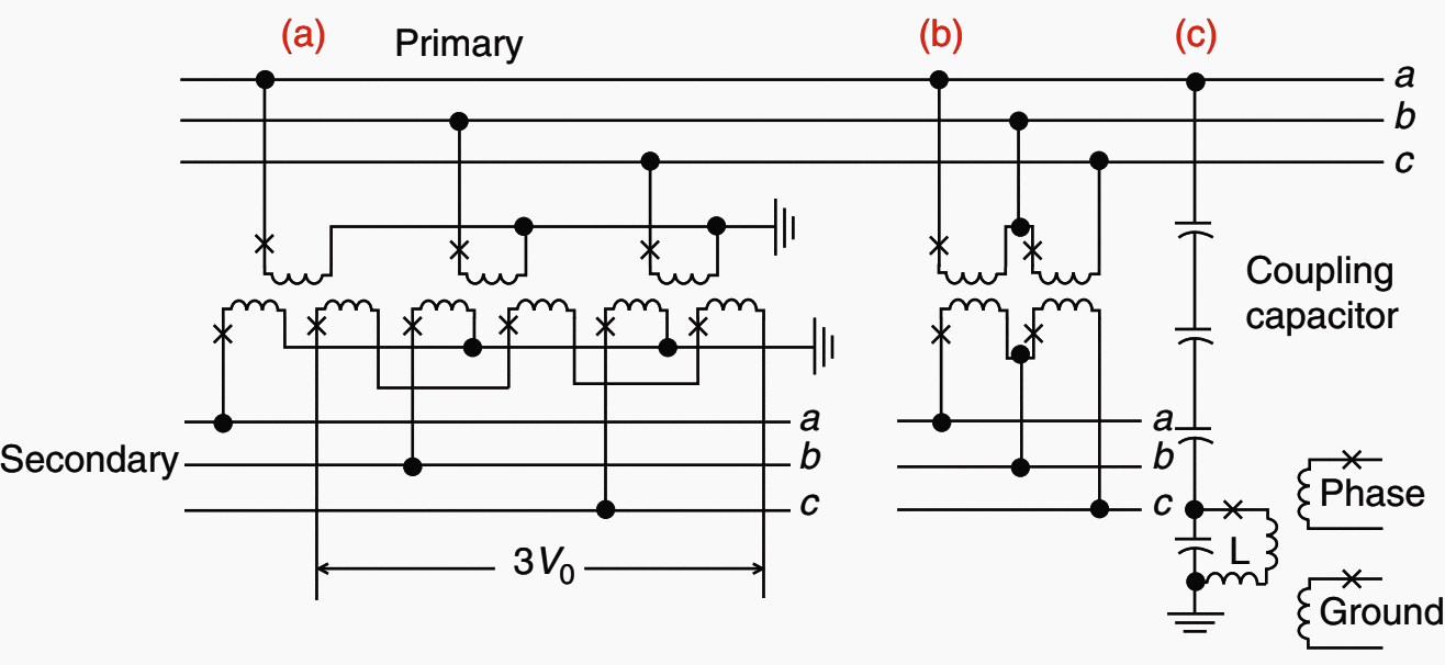
Pmu installation and connection diagram.The instrument transformer Using potential transformers.


CT and PT Connection Diagram Explained - ETechnoG
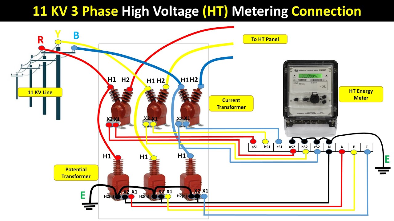
11KV High Voltage HT Metering Connection With CT & PT - YouTube
CT And PT Connection Diagram Explained ETechnoG, 56% OFF

Ct Block Diagram - nibbletips

Great 3 Phase Energy Meter Connection Diagram With Ct And Pt 7 Core

Ct Metering Wiring Diagram - Wiring Draw
![[DIAGRAM] 12470 3 Phase 4 Wire High Side Diagram - MYDIAGRAM.ONLINE](https://i2.wp.com/ctlsys.com/wp-content/uploads/2016/10/ConnDiag-PT-Delta.png)
[DIAGRAM] 12470 3 Phase 4 Wire High Side Diagram - MYDIAGRAM.ONLINE

Circuit Diagram Of Ct